1. DFMEA Definition
DEMEA Full Form – Design Failure Mode Effect Analysis
DEMEA (Design FMEA) it means design failure mode effect analysis. On other hand it is type of failure mode effect analysis that motive is to reduce the product failure.
DFMEA is an practical approach used in the design and product development phase to improve and maintain the quality of product and its research process.
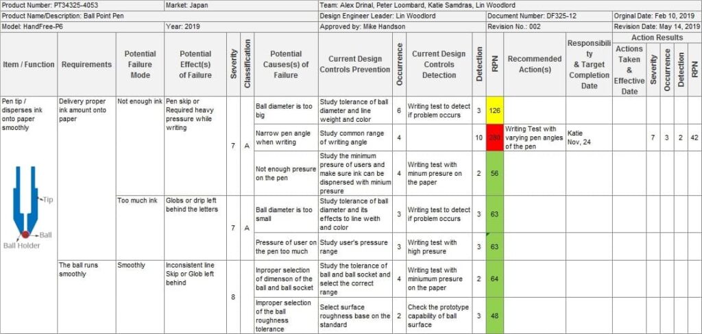
For an Example: Design FMEA Process Sheet of a Ballpoint Pen.

2. Why we need to use Design-FMEA
Quality is very important for customer satisfaction, loyalty and future product purchases. Recent quality scandals involving many companies have shown that serious design issues can damage a company’s reputation or harm its business.
Less serious design problems fail to satisfy customers, delay new product launches, and cost the company financially.
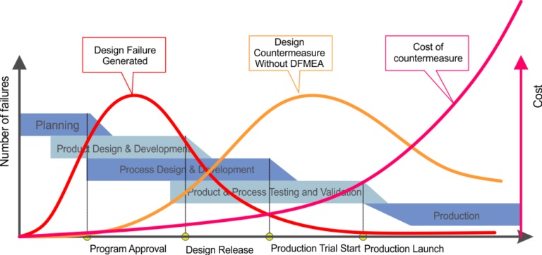
In new product projects, design errors are inadvertently made during the design and product development phases. Without DFMEA almost all errors were detected only during validation and trial production, some only after the start of production.
However, the costs of developing countermeasures in the later phase are much higher than in the previous phase. With DFMEA, countermeasures are considered to coincide with the onset of defects.

3. When will DFMEA be conducted
With DFMEA, organizations can ensure that all design requirements are fully met before production begins and maintain design quality later.
3.1. When to start
For new product designs, FMEA should start with product design before prototypes are produced.
3.2 Verification Time
The team must continually review and update the DFMEA document as the product changes:
Product design changes: Product changes can be a reason for a DFMEA review. In this case, you need to focus on the point of change and the points made.
Quality problems caused by product design: New internal defects or customer returns need to be reflected in the DFMEA to review and consider corrective action.
4. Who will do the DFMEA?
A good DFMEA should be carried out by a multifunctional team and led by a responsible product designer. The departments involved should include design, test analysis engineers, manufacturing, supplier quality, product quality, service, and logistics, among others.

5. How DFMEA is done
5.1 DFMEA Templates
First, a DFMEA template (also known as a DFMEA form) is required. Like other FMEA templates, the DFMEA template consists of two parts: the head and the body.
The header contains general information including but not limited to product name, product number, team member, project manager, customer, document number, and document version.
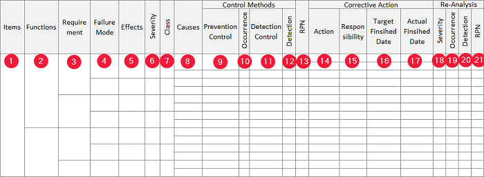
The body contains many columns with links. There are many different FMEA design templates that contain different column names. Multiple columns can be divided or combined, but there is no difference in meaning.

- Items: Item (component, part, assembly) of the product/part to be analyzed. An element has one or more functions.
- Function: Element function. A function has one or more requirements
- Requirements: Functional requirements. The request has one or more potential failure modes.
- Failure Mode: The way an item may fail to meet the requirements. The cancellation policy has one or more potential implications.
- Effects: Possible impact of a potential failure mode on functionality and customers.
- Severity (S): The number in the rating reflects the most severe potential impact of a withdrawal regimen. Severity is rated on a scale of 1 to 10, with 10 representing the greatest risk.
- Class: A special product feature or high risk mode of damage.
- Cause: The reason why the error occurred. Denial regimes have one or more possible causes.
- Preventive controls (in control methods): Design actions to prevent potential causes from occurring.
- Occurrence (C): The number in the rating reflects the probability of damage. Events are rated on a scale of 1 to 10, with 10 being the most likely event.
- Detection control (in control method) Design actions to detect the error or the cause of the error, if any.
- Detection (D): The number in the rating reflects the best method for controlling detection. Detection is rated on a scale of 1 to 10, with 10 being the worst detection ability.
- RPN: (Short for Risk Priority Number) An indication number for the risk assessment process based on severity, incidence and detection. Depending on the RPN and the S, O, D index, the responsible team/person must decide on the corrective action required for each failure mode. The RPN formula is: RPN = S x O x D
- Action: Recommended action to eliminate or reduce the probable cause of the failure.
- Responsibilities: The individual or team/department that must carry out the recommended action.
- Target Finish Date: The date the plan is finished.
- Actual Completion Date: Actual Completion Date.
- Severity: Re-evaluate the severity of the damage mode after corrective action
- Occurrence: Reassess the probability of occurrence after corrective action
- Detection: Reassessment of detection ability after corrective action
- RPN: Recalculation of risk priority number after corrective action
5.2 Meta data of FMEA design
The following documents should be considered as input resources for the FMEA design team:
Block diagram (boundary diagram): A product block diagram shows the physical and logical relationships between product components. Bar charts can be used to identify the elements contained in a DFMEA.
Parameter Diagram (P): P diagram is a structured tool used to describe the physics associated with the design features, input lists, outputs, controls, and noise figures of the target.
Quality History: Can be used to find potential failure modes and confirm the effectiveness of countermeasures in new designs.
Drawings, technical specifications: Can be used to define functions and requirements.
Bill of Materials: List of components/parts of the product.
5.3 Steps to develop FMEA design
When everything is ready, the DFMEA team, templates and supporting documents, you can start executing the FMEA design by following the 9 steps below:
- Define product requirements
- Brainstorming mode for potential bugs
- Impact analysis
- Look for possible causes
- Describe current controls for possible causes
- Occurrence assessment / current status determination
- Calculate RPN and assess the risk
- corrective action plan
- RPN reassessment after corrective action
5.4 DFMEA connection
DFMEA is not a stand-alone document in the product and process development process. To ensure that your DFMEAs are consistent with each other, the information in the DFMEA must be linked to the relevant information in other documents:
PFMEA
The relationship between PFMEA and DFMEA may not be clear because they have different purposes. While PFMEA focuses on processes, DFMEA focuses on products. However, the following links should be kept:
- The product and process characteristics specified in the PFMEA must match the relevant elements in the DFMEA.
- Sometimes the DFMEA and PFMEA fault regimes have the same potential impact. The severity weights associated with the same effect should be the same in PFMEA and DFMEA.
- Potential PFMEA failure regimes that result in product-related impacts should be listed in the DFMEA Potential Failures. In contrast, a potential failure mode in DFMEA caused by a process should appear in the PFMEA Potential Failure Effect.
Design Verification Plans and Reports (DVP&R)
Project inspection plans and reports are plans and reports used to confirm that a system, product, or component meets design requirements. At a minimum, the DVP&R should have test items, criteria, procedures, and sample sizes. DFMEA Prevention and Detection Controls are the input data for the test items included in the Project Verification Plan.
6. Summary
The DFMEA must reflect the current state of the product design and is therefore referred to as a living document. However, keeping DFMEA alive is not easy. This is because of the complexity of DFMEA and its relationship to other documents. Maintaining life in DFMEA is much easier if we use proper DFMEA software like FMEA analysis.


No Comments